Digispark Info
Default Digispark
The default digispark board manager does support Micronucleus version 1.6 and below:
Board Manager: http://digistump.com/package_digistump_index.json
Alternative: https://raw.githubusercontent.com/ArminJo/DigistumpArduino/master/package_digistump_index.json
Flash a ATTiny85 with Micronucleus
avrdude -p t85 -P /dev/ttyUSB0 -c avrisp -b 19200 -U flash:w:t85_default.hex -U lfuse:w:0xe1:m -U hfuse:w:0xdd:m -U efuse:w:0xfe:mATTinyCore
For all Micronucleus versions 2.x and greater the default Digispark board manager won't work. So you either have to flash it down again or use this:
github.com/SpenceKonde/ATTinyCore
Board Manager: http://drazzy.com/package_drazzy.com_index.json
Pinout
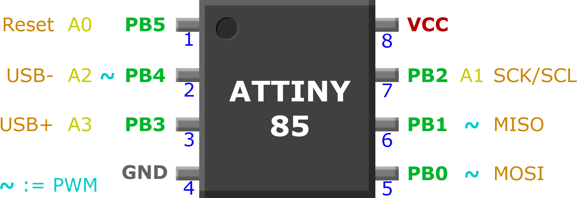
| Pin | Analog | Chip | Functions |
|---|---|---|---|
| PB0 | - | 5 | PWM, MOSI |
| PB1 | - | 6 | PWM, MISO |
| PB2 | 1 | 7 | SCK, SCL |
| PB3 | 3 | 3 | USB+ |
| PB4 | 2 | 2 | USB-, PWM |
| PB5 | 0 | 1 | Reset |
| VCC | - | 8 | 1.8V - 5.5V |
| GND | - | 4 |
Use Reset pin 5 as input
If the reset pin is below half of VCC a chip reset is triggered. You can either flash the chips fuses to deactivate this behaviour (which requires a high-voltage flasher to undo) or use the pin as analog input for values above 1/2 VCC.
For a simple input button you can use a voltage divider circuit to switch between full VCC and less but above 1/2 VCC:
VCC o───[10k]───┐
                ├───o Pin5
                o
                 \- Pushbutton
                o
GND o───[51k]───┘
The code can then read the analog input of pin 5 which is analog pin 0:
void setup() {
  // Prepare Pin 5 for analog button input
  pinMode(5, INPUT);
}

void loop() {
  // Read the analog value on pin 5 (analog 0)
  // 1024 is high, lesser is low, <512 would trigger reset
  if (analogRead(0) < 950) {
    // Button on pin 5 is pressed
  }
}
USB Circuit
USB

VCC  o──[2k2Ω]─┬──────────o 8 VCC
USB- o─────────┼───[68Ω]──o 2 PB3
USB+ o──────┬──╫───[68Ω]──o 3 PB4
GND  o──┐   ╧  ╧       ┌──o 4 GND
        │   Z  Z       │
        │   ┬  ┬       │
        └───┴──┴───────┘    Z := Zener 3V6