Flash ATtiny85
Connect the hardware
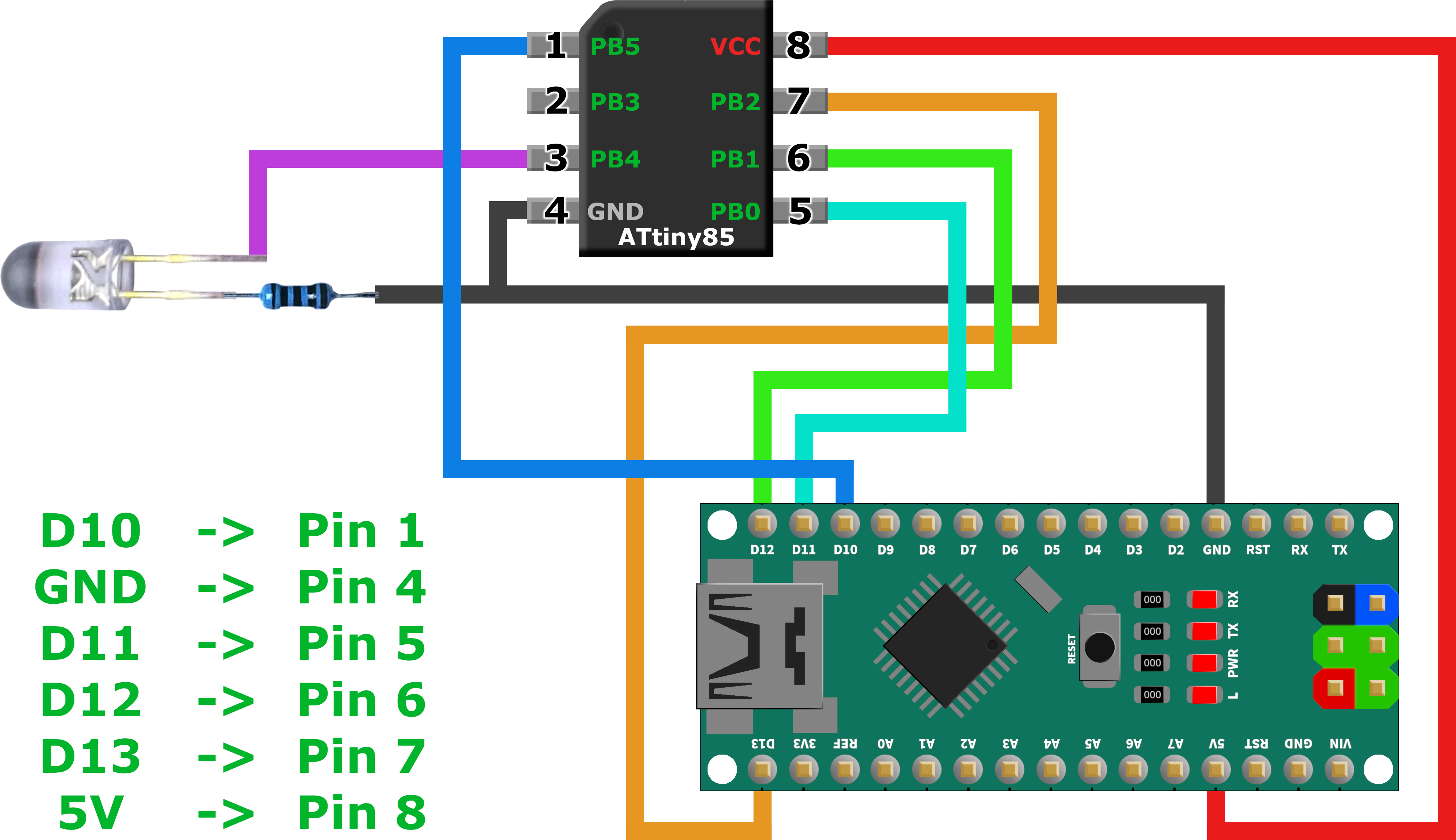
| Arduino Pin | ATtiny Pin | Digital | Arduino Pin | ATtiny Pin | Digital | |
|---|---|---|---|---|---|---|
| D10 | 1 | PB5 | VCC | 8 | ||
| D13 | 7 | PB2 | ||||
| D12 | 6 | PB1 | ||||
| GND | 4 | D11 | 5 | PB0 |
Prepare Arduino IDE
File -> Preferences
- Additional Board Manager URLs:
https://raw.githubusercontent.com/damellis/attiny/ide-1.6.x-boards-manager/package_damellis_attiny_index.json
Tools -> Board -> Board Manager
- Install:
attiny
Tools -> Board
- Board: "ATtiny Microcontrollers" ->
ATtiny25/45/85 - Processor:
ATtiny85 - Clock:
Internal 16 MHz - Port: Your Arduino ISP Port
- Programmer:
Arduino as ISP - Burn Bootloader!!! (To apply clock and other flags)
Test your setup with a simple blink program
void setup() {
  pinMode(4, OUTPUT);
}

void loop() {
  digitalWrite(4, HIGH);
  delay(500);
  digitalWrite(4, LOW);
  delay(500);
}